This is a Disclaimer!!!
Kevin Hawkins and Terry Baker provide an internet information source that has been created for educational and communication purposes. The procedures for rebuilding a GTS1000 ABS Hydraulic Pump are not approved by Yamaha Motor Corporation, U.S.A. Terry Baker and Kevin Hawkins are not responsible or liable for any injury, damages or other consequences that result from individuals who view this forum and implement the suggestions, opinions, or techniques discussed on this page.
ABS REBUILD PROCEDURE:
THINGS TO HAVE:
-Arrange to have access to a metal lathe (preferably) or a drill-press
(alternate)
-Brake cleaner
-WD-40
-Lots of blue shop towels
-Fine bronze or steel wool
-Shop Manual
-At least 1 qt. brake fluid. (I used Valvoline synthetic DOT3/DOT4
compatible.) Any DOT4 or DOT5.1 is OK--DO NOT use DOT5.0
-Speed bleeders, mityvac, or some other type of brake bleeding aid.
-New copper crush washers (8)
-Bags, dishes, etc. to keep track of loose parts
-Battery or battery charger and wires with alligator clips
-Naval jelly, dremel tool, etc. (Whatever you have to remove rust from
metal parts)
GENERAL TIPS: If you don't lose anything and your o-rings are in good shape, you shouldn't need any spare parts. It's a tear-it-down, clean-it-up, and put-it-back-together affair. Be very careful, have lots of blue shop towels available, and a clean workbench. Spend time with the shop manual studying what they have to say about the ABS system--it really is helpful. There are many small parts and there are no exploded diagrams of how this thing goes together. Take your time and DON'T LOSE ANY PARTS.
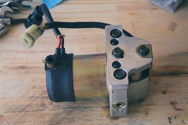
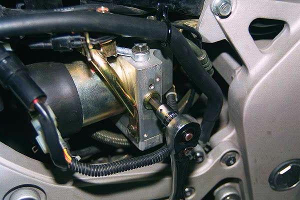
PROCEDURE: 1) Remove HU from the bike. (shop manual is really good here.) I used a plastic baggies and rubber bands to seal the ends of the brake lines to prevent brake fluid from dripping everywhere. I wasn't careful enough--I bubbled quite a bit of paint on the swingarm.
2) Remove electric motor. Move rubber cap--remove two long bolts
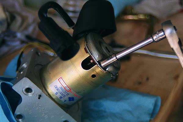
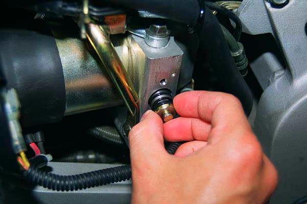
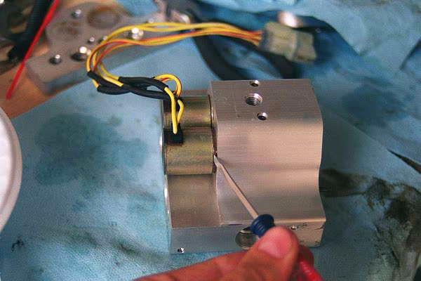
3) Remove 8mm hex nuts. Note: In the picture, I removed the plug while the HU was still in the bike. The next step is much easier to do with the HU on the bench.
4) Push out return pumps from the inside where the motor mounted.

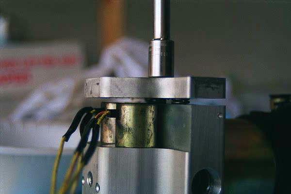
5) Slowly remove the 12mm bolts and the aluminum plate on bottom of the aluminum housing, exposing the buffer chambers. DO NOT remove the rubber plugs. The springs and pistons are the same--the holes they are mounted in are different depths--the deeper is for the front brake circuit.
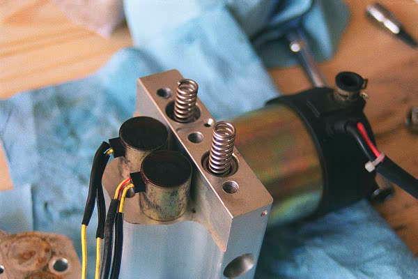
6) Remove the buffer chamber pistons. This can be a real pain--I was able to work a finger inside and "pull" the piston out.
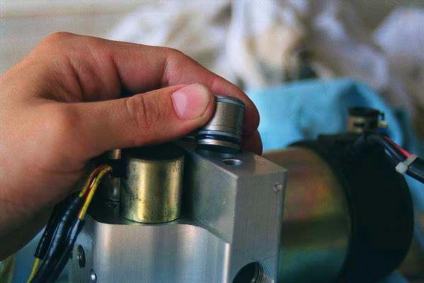
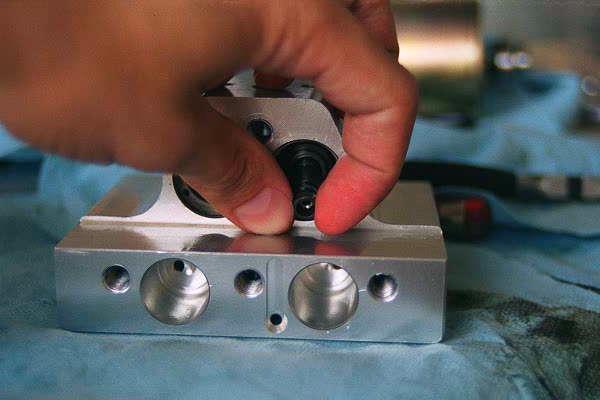
7) Mark the solenoid valves and housing such that you get the right one back in the right place. (I used an awl to make one small scratch on one solenoid and two scratches on the other, with matching scratches on the housing.) Use a small screwdriver to pry out the solenoid valves--do this such that you're removing them upward with the housing on the bench--the "spools" are behind the solenoid valves with springs holding them in place and they can fall out. These are held in place by o-rings and the aluminum plate from step 5--they can be sticky, just take your time and work them out.
8) Remove the springs and spools behind the solenoid valves--pay close attention to the orientation of the spool as you remove it--you may have to turn the housing upside down and let them slide out. Once removed, look inside the spool and you'll see the tiny orifice. If this gets plugged, the system is hosed--that's why almost any gunk or particles cause such a mess.
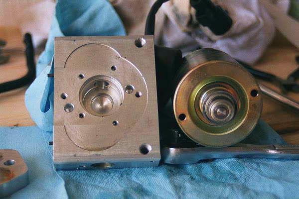
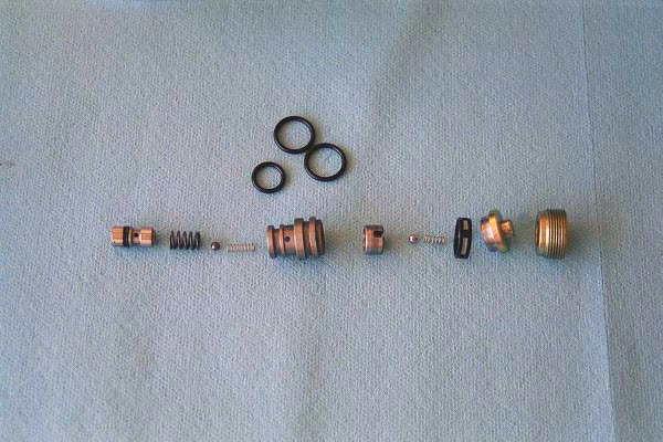
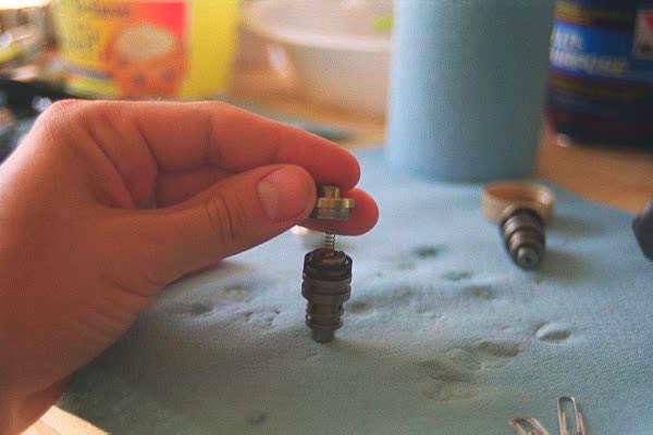
9) Disassemble the return pumps. Look at picture "disassembled return pump 1" below. These parts are a precision press-fit and need to be disassembled in a linear manner. I didn't take pictures (unfortunately) as I was taking them apart. If on a lathe, chuck one part in the headstock and use the drill bit chuck in the tailstock to hold the parts and then retract the tailstock while slowly rotating the headstock back and forth. Do this slowly as there is a spring and steel ball inside that can easily be lost. If you use a drill press, hold one part in a drill-press vise clamped to the table and the other part in the chuck. Retract the chuck while slowly rotating it back and forth. If you don't have access to either of these tools, find a machine shop--they should do it for only a few bucks. DO NOT use pliers and a bench vise or whatever--remember that spare parts are at least a week away--let me know if you end up needing the contact info. After the parts have been cleaned, you can carefully tap them back together using a mallet or something. Note that the shorter of the two small springs goes under the cap. Clean these parts. (see step 11 for hints.)
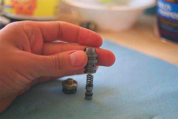
10) Re-assemble the return pumps. Apply a little brake fluid to the o-rings to keep them wet. Balance the small spring on top of the steel ball. Hold the parts as in the first picture and slide the one part over the other. Look through the hole in the top to see if the small spring is in its slot--If it's not, start over. Once these parts are together, move on to the other picture. Once again, balance the small spring on top of the steel ball and slide the cap down over the top. The piston should move freely inside the other parts. After having done this, you'll understand why it's not a good idea to EVER remove the 8mm nuts while the HU is on the bike.
11) Break down all the other parts and clean, clean, clean. Be careful using brake cleaner as it may attack the o-rings--I used WD-40. Use the bronze (steel) wool to scrub off as much corrosion as you can from the steel parts. You may use naval jelly or a Dremel tool, whatever. Spray clean all of the passageways in the housing.
To remove o-rings, use a blue-towel to grip the sides of the o-ring and push up. You should be able to form a loop that you can get ahold of--try to avoid using sharp objects to get under the o-ring and pry it off--bad habit.
Hook up the solenoid valves to a battery or charger--lead orientation doesn't matter--to open the valve. (You'll hear a tiny "click") Spray WD-40 or something through the solenoid valve to make sure the passageway is clear.
12) To re-assemble: Reverse the disassembly sequence with the exception of steps 2,3,4. Re-install the electric motor before you install the return pumps and the 8mm hex nuts.
Other pointers--Try to keep the parts separated for each side. I used baggies and/or old butter dishes, etc. Just keep the parts separated and grouped. Remember that you don't have parts break down diagrams and/or spares readily available (except for the o-rings.)
Use new copper crush washers when re-installing the unit. Also, bleed as best you can, run the self-diagnostic 3 or 4 times and bleed again. I had to remove the front caliper and rotate it over the front of the disk to get the nipple higher than the hose. I couldn't get all the air out with it installed. Yamaha has a special tool for this--it looks like a boomerang. See if your dealer has one and will let you borrow. Otherwise, I used big zip ties and hung the thing from the front sub-frame.
At the HU, the hose ends are either bright or black for in or out of the HU to help make sure the right one goes to the right place. I hope you have speed bleeders or something similar to help out. I used Valvoline synthetic DOT3/4 compatible fluid--buy at least a quart. You'll see in some of the photos that I started tear-down while it was in the bike. It's a lot easier if you follow the steps above.